
eRIC & eRA GPS Evaluation Kit
Test & Evaluation Kit for all of LPRS's radio modules
The eR Evaluation Kit provides a platform for the test and evaluation of all LPRS's eRIC & eRA radio transceivers. The kit allows demonstration of the transfer of serial data over the RF link and simple manual / auto transmit / receive modes. The addition of GNSS (GPS) positioning technology allows users to quickly assess how far they can transmit data as well as providing a reference design for GNSS enabled LPRS radio applications.
Key Features of the eR-EVK
-
Compatible with any LPRS radio module
-
On-board GPS (GNSS) for easy range testing
-
Battery powered
-
Reference design available
Kit Contents
-
1 x eR-EVK GPS enabled board.
-
1 x eR-EVK PC USB board.
-
2 x eRIC or eRA modules of your choice.
-
2 x Dipole antenna, 2 x USB cable, 3 x AA batteries.
Part Number |
Suitable for |
Download |
|
eR-EVK |
eRIC4, eRIC9, eRIC-LoRa |
|
|
eR-EVK-SIGFOX |
eRIC-SIGFOX |
|
|
eR-EVK Evaluation Tool Software (PC) |
All modules |
|
eRIC Evauation Kits are available for two regions: eRIC4 for European 433/4MHz licence exempt ISM band, eRIC9 dual band for European 868MHz and USA 902 - 928 MHz licence exempt ISM bands.
More about the eRIC Evaluation Kit
Using this kit together with the supplied ‘easyRadio Companion’ software, connection can be made to the eRIC modules allowing the default operating frequency (channels), RF power output, ‘Over Air’ and Host serial communication rates to be configured and changed.
The eRIC evaluation board is provided with both a ‘spring pinned socket’ and an area/pads for the alternative and permanent SMD mounting of eRIC. All eRIC pins (1–23) are brought out to Single In Line (SIL) turned pin sockets allowing easy interconnection to external prototype/development circuitry via jumper wires.
The board can be powered either by the PC USB connection (5V) or for portable/remote range testing by the supplied 9V PP3 battery. An on-board FT230 device provides a USB to serial connection to a host PC or other device and is used both for sending and receiving serial data to eRIC, sending configuration commands and at a later stage for programming the ‘flash’ memory of the device using the embedded bootloader software. Status LEDs are used to indicate presence of board power and both transmitted and received serial data activity. Four of the I/O pins are connected to pushbutton switches/LEDs to provide useful user input/outputs for test and demonstration during later application development.
Users in the United States using eRIC9 modules should permanently connect eRIC pin 14 (Frequency Select Pin) to 0V (Gnd). This action will change the default operating frequency from 869.75 MHz to 915.00 MHz and reduce the default transmit power output from +7dBm to -3dBm.
Relevant to eRIC RF Evaluation Kits
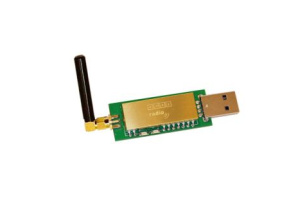
easyRadio Breakout Boards
Quick & Easy Testing of eRA & eRIC modules.

easyRadio Arduino™ Evaluation Kits
Arduino Kits, Compatible Shields and the eRIC Nitro
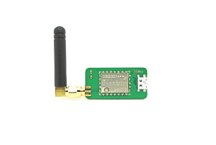
easyRadio USB RF Dongles
Pi Compatible easyRadio USB Dongles for RF Testing & Design

Useful RF Information
Useful RF Information